Low Power Triggered Transmitter and 120V Receiver Module Kit Feed your Load

Question from customer:

“I am looking for a 120V rf transmitter module, single channel that is normally open. I want it to transmit signal when power is applied. I want to pair a 120V rf receiver relay with it, normally open. When I apply power to the transmitter, I want the receiver to close the relay feeding my load. You have a remote control system that meets this need, but I would like to hardwire a 120V switch rather than use a remote. ”

Answer:

We recommend this 1 channel 220V universal receiver (S1U-AC220) and the low current triggered transmitter (CB-2V) with a 120V/12V power adapter. The receiver is normally open and closed contact, so you can wire AC 110~240V or DC 0~28V actuated device, such as lights, motors, fans, electrically operated doors/locks/windows/blinds/cars or other appliances. The transmitter is DC power 5~28V input, that is to say, you need supply 5-28V power to this transmitter.

remote-control-kit

You can connect this adapter to the transmitter. And your device will be wired to receiver as following picture.

transmitter-circuit

1_09

When 120V power is applied to this adapter, adapter will convert ac power to dc power output so that transmitter will trigger the receiver and the receiver will close the relay to feed your load.

120V Winch Motor is Controlled Remotely by Inversion Motor Controller with Time Delay Function

Question from customer:

We are looking for a 120vac powered remote control for winch. We need 1 motor control 120vac with ability to stop when limit switch reached. Also like delay for start direction of ac motor.

ac 220v winch

Answer:

Forward &Reverse Motor controller is 110V~220V power actuated, which also enjoys time delay function and limit switch. It focuses on capability of motor forward-reverse-stop. Wireless signal pass through walls, floors, doors and other obstacles if you remote control your winch motor within a reliable distance from any places. With time delay function, the working time can be adjusted from 10 to 60 seconds. What’s more, the limit switch can prolong or shorten delay time through its clockwise or anti-clockwise rotation. It really meets your need.

1

Wiring and operation will be explained in more detail from following procedure and picture.

Wiring procedure:

Connect the live wire to the “L”, and the zero wire to the “N”. Connect AC motor to the “OUT” and the zero wire. You can exchange output wires of motor to change the rotating direction of motor.

1_03

Operation:

Press button ▲: Light 1 shines, motor rotates in the positive direction, and it will stop after a certain delay time.

Press button ▼: Light 2 shines, motor rotates in the reversal direction, and it will stop after a certain delay time.

The delay time of positive / reverse rotation can be adjusted from 10 to 60 seconds. Turn R1/R2 clockwise, prolong the delay time. Turn R1/R2 anti-clockwise, shorten the delay time. When you press button ▲ or button ▼, the motor starts to rotate; It will stop after the delay time is expired.

When the rotation is overdone, if switch S1 or S2 is activated, the motor will stop automatically.

After press button ▲, you must press button ■ to stop the motor firstly, and then press button ▼.

If you pull out the Jumper of the receiver, you can press directly button ▼ after press button ▲.

220 V relay output wireless receiver & transmitter of remote control lamps on/off

Question from customer:

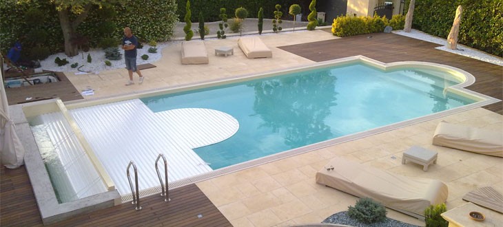
My company import different led products, so for manage some led garden products and led swimming pool lamps, we need:

– system of switch with remote control who can switch on and switch off current 12 volts or 220 volts (we can install your control box before power supply if you have 220 volts system or we can install after power supply if you have only 12 volts ac system.)

Answer:

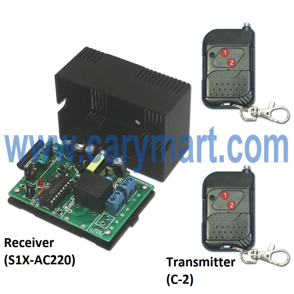
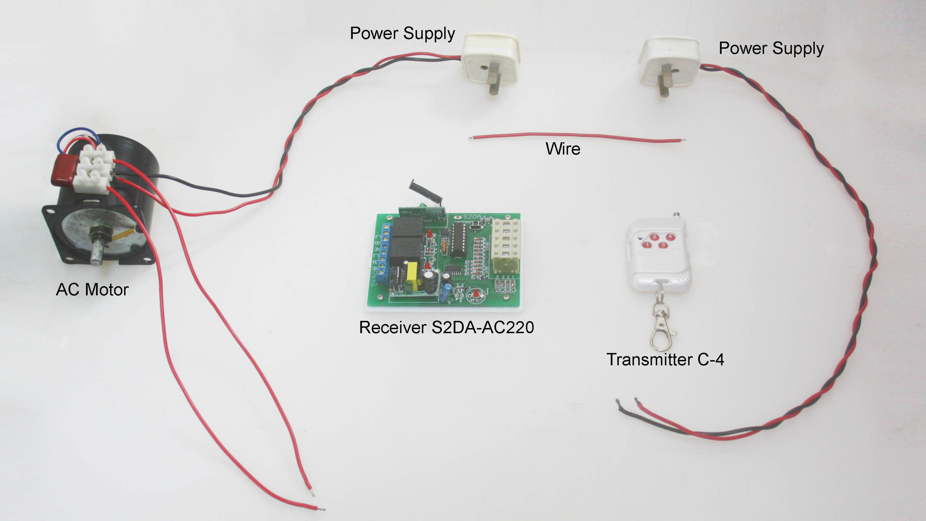
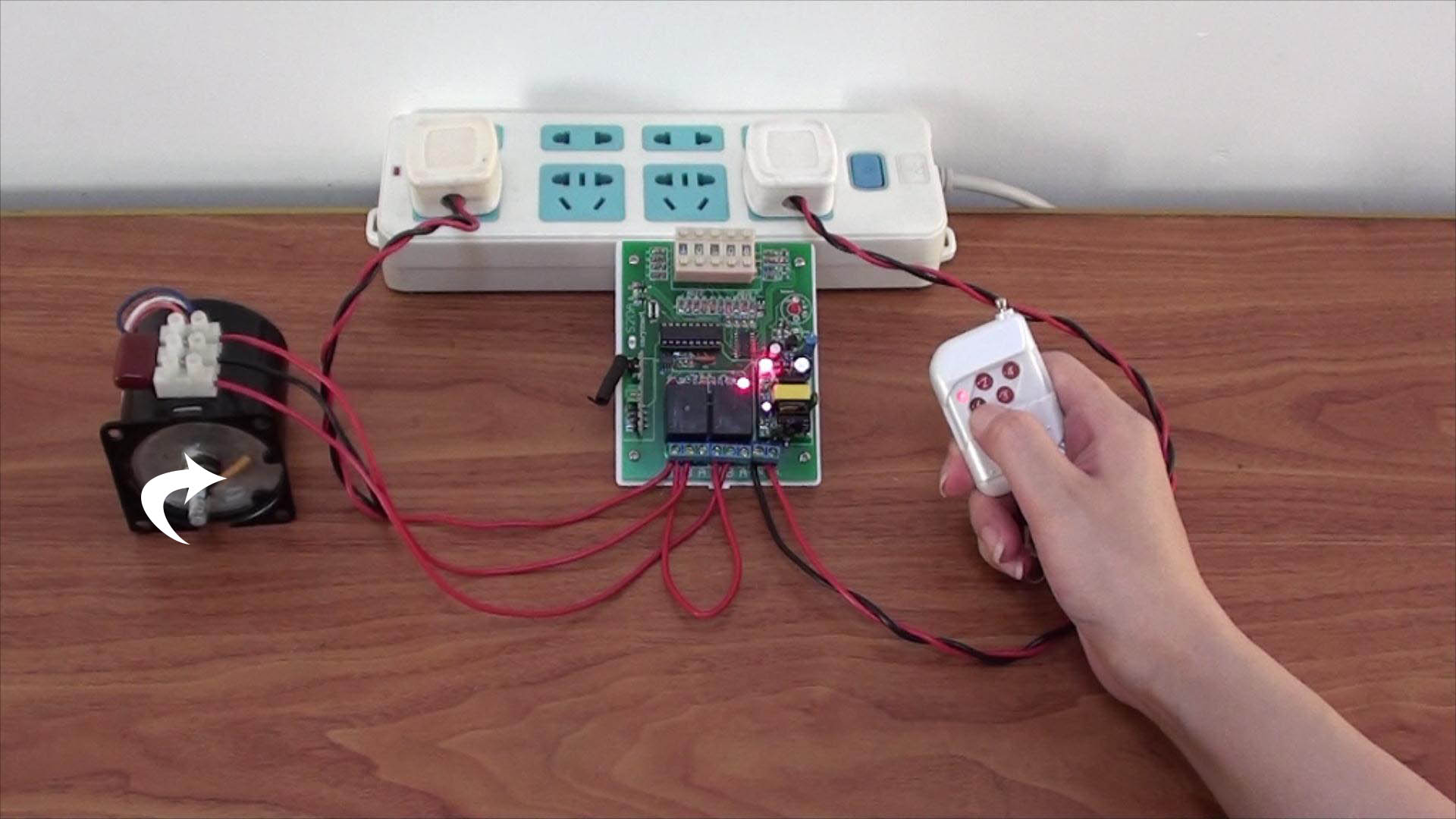
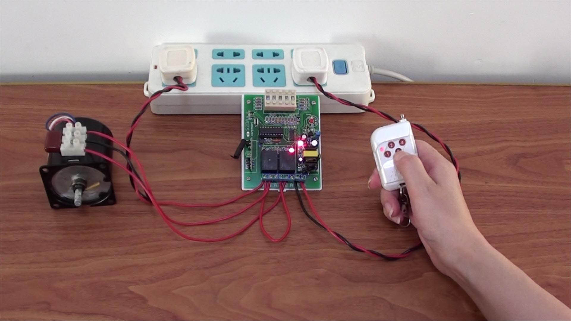
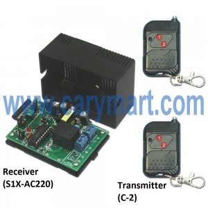
We advise you use the wireless remote control system according to your requirement. It is model: S1X-AC220 & C-2. The receiver’s (S1X-AC220) working voltage is AC100~240V. The transmitter’s(C-2) remote control distance is 100m/300ft theoretically. The transmitter controls the receiver. If you mount the receiver to the equipment which will be controlled, the wireless transmitter can turn on/off the equipment by remote control the receiver. For example, you can mount receiver to your swimming pool lamps, then you can turn on/off the lamps through pressing the buttons in the transmitter.

u=2722728786,3211226477&fm=23&gp=0

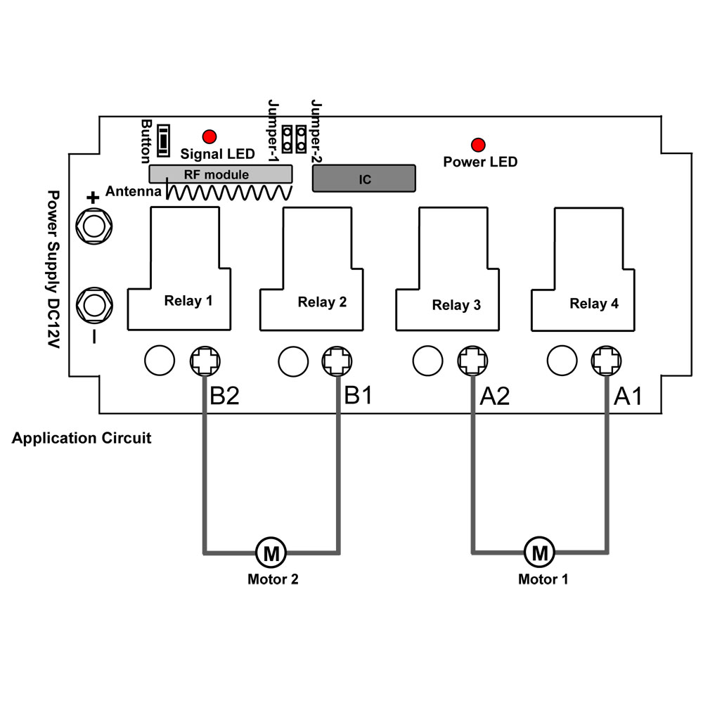
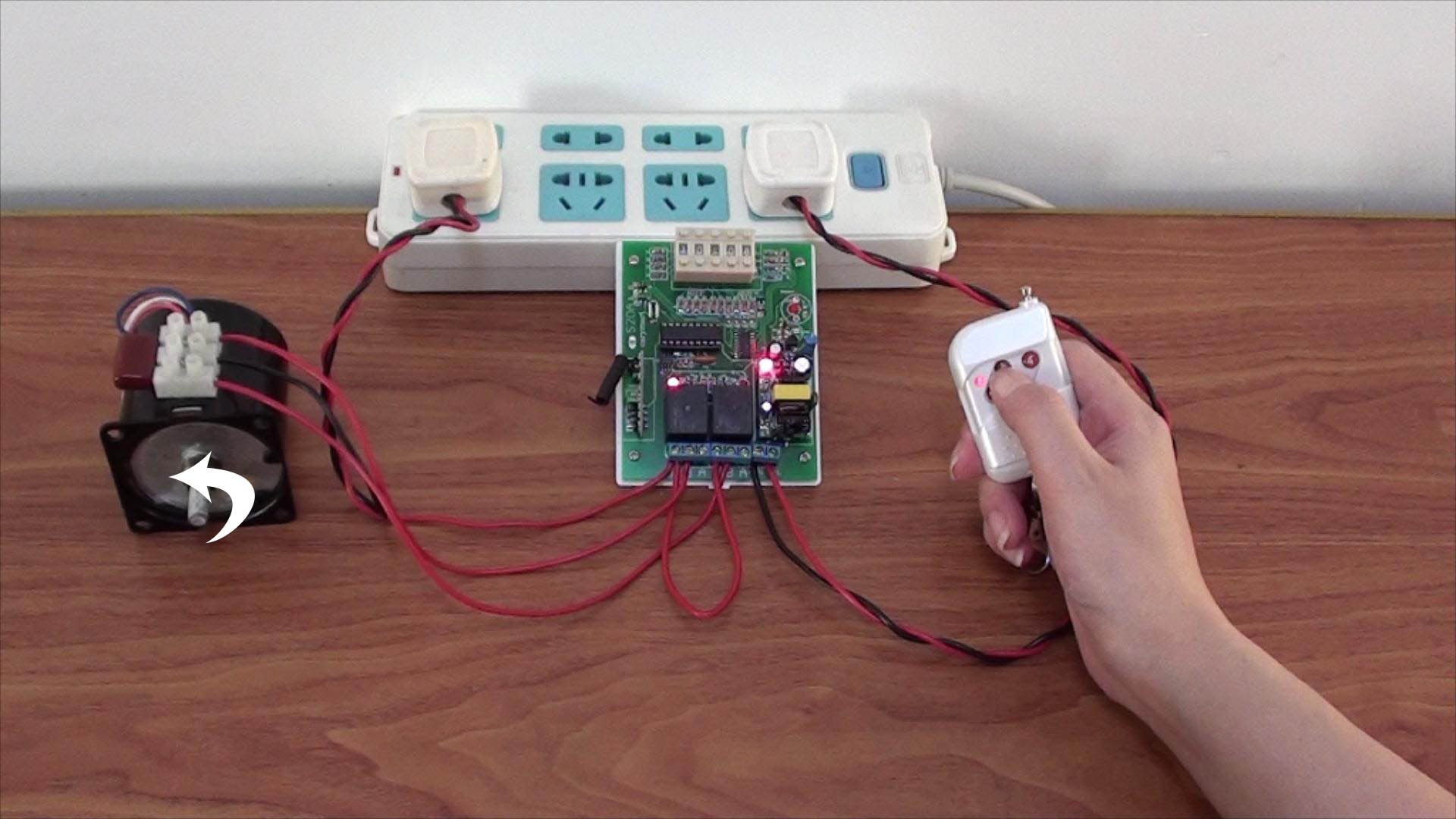
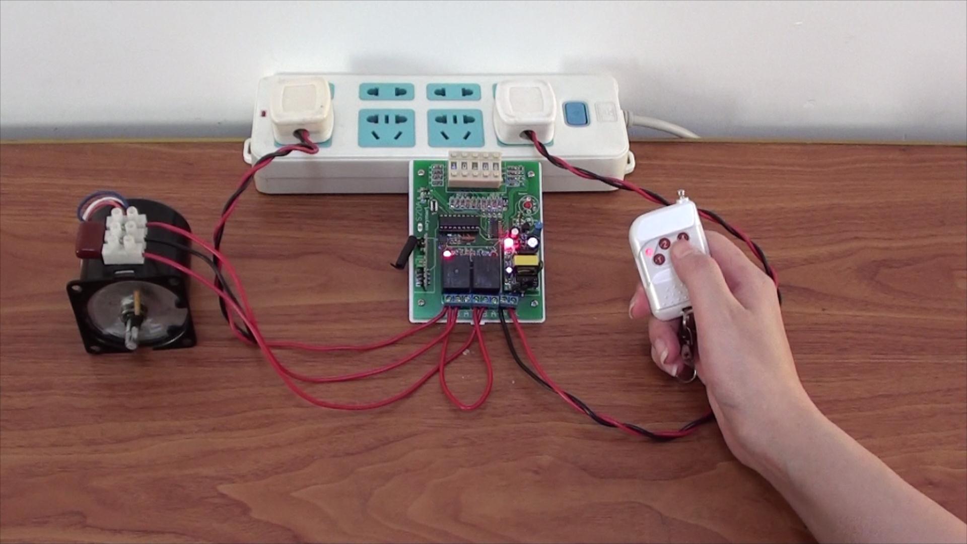
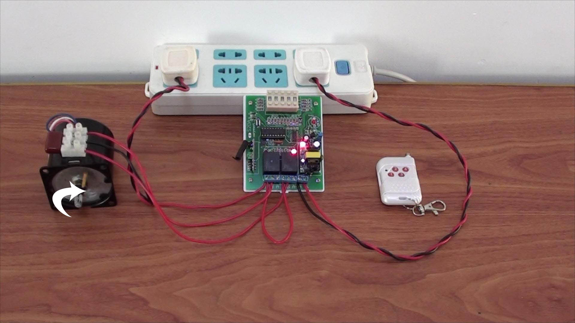
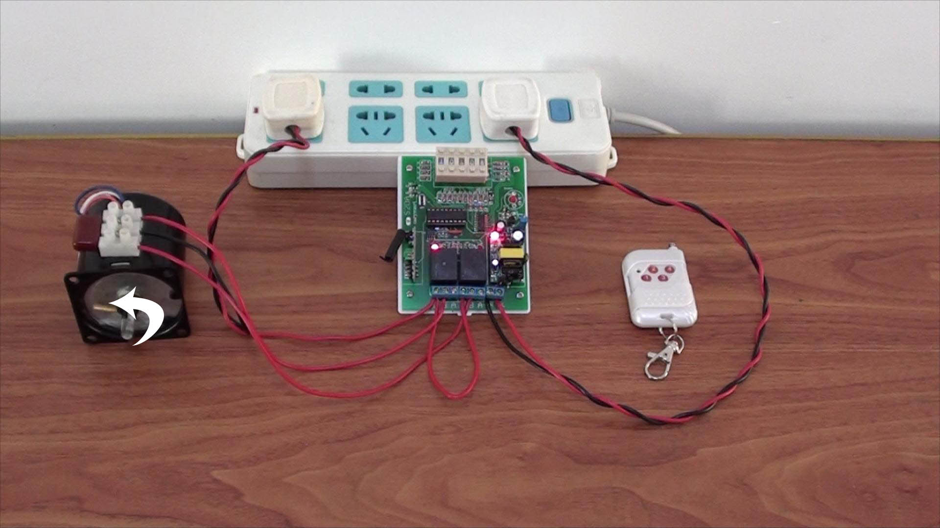
Besides, the system can also control motors, fans, electrically operated doors /locks/ windows/blinds/cars or other appliances with AC 100~240V. When you remote control the appliances, the transmitter can launch wireless RF signal to the receiver. The wireless RF signal can pass through walls, floors and doors.

1_03

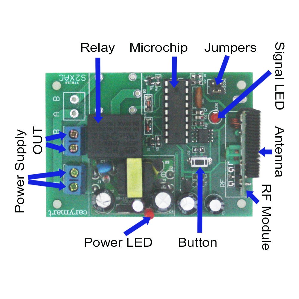
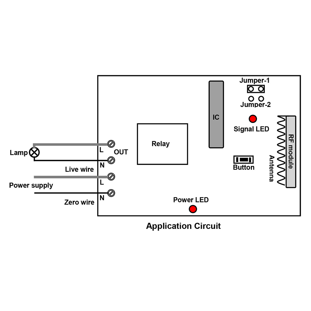
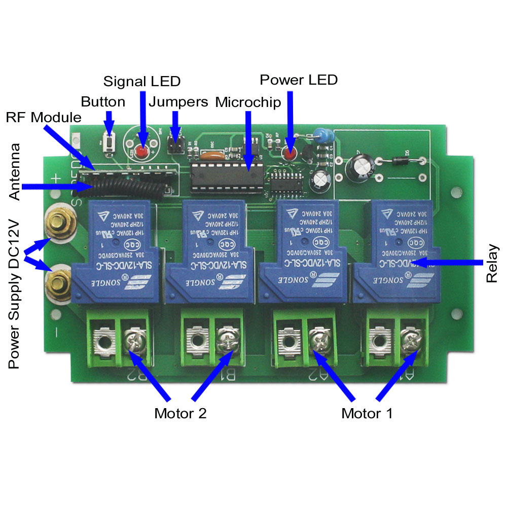
Here is the circuit diagram of the receiver. You can connect one lamp to the “N & L” output terminal of the receiver. Then supply power to receiver by connecting live wire and zero wire. When you press the buttons in the transmitter, you can turn on/off the lamp by wireless remote control.

1_05 1_08

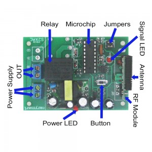
There are three control modes for the wireless remote control system: toggle, momentary, latched. You can set any one mode of three control modes as following operation:

Setting control mode Toggle: Only connect Jumper-2.
Press button 1: Turn on the lamp, terminal OUT outputs AC power.
Press button 1 again: Turn off the lamp, terminal OUT no output.

Setting control mode Momentary: Only connect Jumper-1.
Press and hold button 1: Turn on the lamp terminal OUT outputs AC power.
Release button 1: Turn off the lamp, terminal OUT no output.

Setting control mode Latched: Do not connect Jumper-1 and Jumper-2.
Press button 1: Turn on the lamp, terminal OUT outputs AC power.
Press button 2: Turn off the lamp, terminal OUT no output.

     Finally, you can enter into our website for knowing more something about the wireless remote control system as following:

Model: 0020392(S1X-AC220 & C-2)

Website:

http://www.carymart.com/

http://www.carymart.com/1ch-ac-110v-220v-power-output-radio-controlled-switch-toggle-momentary-latched-mode-p-1379.html


30A wireless High capacity switch remote control a linear actuator

Question from customer:

Could you tell me the amp load rating for these, as I might have to go with the high capacity switch that can handle a amp load of 30. I am using them to power a linear actuator that has a draw of 20 amps. Maybe the high amp load kit is the correct one?

Answer:

We recommend the high amp load kit to you according to your requirement. It is model: S2PF-DC12/24 & CV-6-2. The receiver (S2PF-DC12/24) is 2 channels and the maximum working current is 30 A/ channel. The transmitter (CV-6-2) has 6 buttons and it can wireless remote control receiver. You can connect the linear actuator with motor to the high capacity switch (receiver) firstly. When you press the buttons of transmitter, the linear actuator with high capacity switch will run through the motor rotates by wireless remote control.

1_01  LAN3A_L


Besides, the high amp kit can control DC motors of rolling blinds / doors, projection screens, awnings, pumps, winches, conveyors or other appliances and mechanicals with voltage DC12V / 24V. You can connect the motor to the high capacity switch (receiver). After you press the buttons in the transmitter, the appliance can be activated by the motor rotates in positive or reversal direction.

Here is the circuit diagram of the high amp load kit. If you would like to remote control one linear actuator, you should connect the motor to output terminal “A1 & A2” or “B1 & B2” of high capacity switch (receiver). Of course you can also connect two motors to it, if you want to remote control two linear actuators at the same time. Then supply power to the high capacity switch (receiver).

1_06

The high amp load kit has two control modes: lathed, momentary. You can set one of two modes as following operation:

Setting control mode Latched: Do not connect Jumper-1 (CN1) or Jumper-2 (CN2)
Press button ▲ on the left: motor 1 rotates in positive direction,
Press button ▼ on the left: motor 1 rotates in reversal direction
Press button ■ on the left: motor 1 stops
Press button ▲ on the right: motor 2 rotates in positive direction
Press button ▼ on the right: motor 2 rotates in reversal direction
Press button ■ on the right: motor 2 stops

Setting control mode Momentary: Only connect Jumper-1 (CN1)
Press and hold button ▲ on the left: motor 1 rotates in positive direction
Release button ▲ on the left: motor 1 stops
Press and hold button▼ on the left: motor 1 rotates in reversal direction
Release button ▼ on the left: motor 1 stops
Press and hold button ▲ on the right: motor 2 rotates in positive direction
Release button▲ on the right: motor 2 stops
Press and hold button▼ on the right: motor 2 rotates in reversal direction
Release button ▼ on the right: motor 2 stops

1_03

The high amp load kit can be used to wireless remote control the linear actuator up or down. If you want to know more something about the high capacity switch, you can enter into our website and search the product as following:


Model: 0020481 (S2PF-DC12/24 & CV-6-2)


Website:

http://www.carymart.com/


http://www.rfcontrolsystem.com/index.php?main_page=product_info&cPath=166_411&products_id=1310

2 Channel Time-Delay Remote Controller Controls Pool Rolling Shutter Open and Close

There are various types of pool rolling shutters such as winter shutters, solar shutters, and safety shutters. All kinds of shutter can prevent leaves or other things falling in pool. Winter pool shutter can keep water warm when winter comes. Safety pool shutter can prevent accidental drowning, especially for children. No matter any purposes for pool shutter, it is most important for pool shutter to be convenient to you. So maybe you really need to your retrofit your pool rolling shutter instead of manual control. You can remote control your existing shutter motor to realize open and closed.

pool shutter

You may wonder how to do this. Please see the following.

You will see the 2 channel time-delay remote control kit (S2DA-AC220+C-4), ac motor or other gadgets.

1 x 2 channel delay time adjustable receiver (S2DA-AC220)

1 x 4-button transmitter (C-4)

AC power supply

Wire

material

You can see the wiring diagram. AC motor is supposed to connect to common terminal B. Live wire is connected to normally open terminals C. And neutral wire is connected to AC motor.

wiring diagram

wiring

Here comes to operation

At first, we set delay time 8 seconds for relay 1 and 10 seconds for relay 2. Then switch on power.

Press button 1, the motor rotates continuously in the positive direction.

button 1 positive rotation

If we want to interrupt the rotation, we can press button 3, the motor stops rotating immediately.

button 3 stop

Press button 2, motor rotates continuously in the reverse direction.

button 2 reversal rotation

If we want to interrupt the reverse rotation, press button 4, the motor stops right away.

button 4 stop

Time Delay Mode

Press button 1, the motor positive rotation will last 8 seconds which is set in advance, then stops rotating.

button 1 time delay

Press button 2, the motor reverse rotation will last 10 seconds which is preset, then stops rotating.

button 2 time delay

Video: